
Heavy Lifting Technology
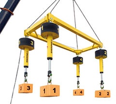
The SHAS-Series Synchronous Hoist System is a below-the-hook sling adjuster (hydraulic turnbuckle) comprised of multiple self-contained, PLC-controlled hydraulic lifting devices. The system enables a single crane to precisely position heavy and unbalanced loads. Each of the lifting devices includes a double-acting hydraulic push pull cylinder with an integrated pump and controls. Integrating the pump eliminates the need for an external power pack and hydraulic hoses.
The wireless remote control ensures a single operator is able to control the SyncHoist while remaining at a safe distance. The operator has full control over load handling; each cylinder can lift or lower independently. The system can perform several types of movements including synchronous lifting and lowering, balancing, and tilting, all of which can be pre-programmed.
| Capacity | Total Load |
Cylinder Stroke |
Model Number 1) 400-500 VAC, 2) 3ph – 50-60Hz |
Control System |
Motor Size |
Dimensions (mm) |
Weight | ||||||
|---|---|---|---|---|---|---|---|---|---|---|---|---|---|
| ton (kN) | ton (kN) | (mm) | (kW) | A | B | D1 | D2 | E | H | J | (kg) 3) | ||
| 4 x 110 (4 x 1078) |
440 (4312) |
1000 | SHAS 4 11040 WE | Wireless | 4 x 4,0 | 1855 | 2855 | 1063 | 315 | 85 | 540 | 124 | 1183 |
| 1500 | SHAS 4 11060 WE | 2355 | 3855 | 1063 | 315 | 85 | 540 | 124 | 1448 | ||||
| 4 x 225 (4 x 2204) |
900 (8820) |
1000 | SHAS 4 22540 WE | Wireless | 4 x 8,0 | 2140 | 3140 | 1235 | 420 | 142 | 580 | 190 | 3219 |
| 1500 | SHAS 4 22560 WE | 2640 | 3640 | 1235 | 420 | 142 | 580 | 190 | 3414 | ||||
1) Standard with 4 lifting points. For more or less lifting points contact Enerpac.
2) WE = with European electrical wiring. Change into suffix “WU” for US-market. Example: SHAS 4 11060 WU.
3) Weight per cylinder.

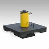
Capacity per Lifting Point
50 – 200 ton
Stroke per Stage 150 – 161 mm
Max. Pressure 700 bar
A Simple Solution to Incremental Lifting
- Climbing jacks include integral tilt saddles with maximum tilt angles up to 5˚
- Large base with anti-rotation rod for stability and safety
- Built-in safety valve prevents accidental over-pressurization
- Feature to install stroke sensor
- Ideal in combination with EVO-Series synchronous lifting pumps
- Baked enamel finish for increased corrosion resistance
- CR400 couplers included on all models.
| Cylinder Capacity |
Stroke | Model Number |
Max. Cylinder Capacity (tons) |
Cylinder Effective Area (in2) |
Oil Capacity (in3) |
Weight | |||
|---|---|---|---|---|---|---|---|---|---|
| (tons) | (in) | Push | Pull | Push | Pull | Push | Pull | (lbs) | |
| 55 | 5.91 | BLS-506 | 55 | 12 | 11.04 | 3.33 | 67.80 | 20.44 | 375 |
| 105 | 6.34 | BLS-1006 | 105 | 48 | 20.66 | 9.64 | 136.57 | 63.77 | 695 |
| 154 | 5.94 | BLS-1506 | 154 | 74 | 30.71 | 14.79 | 188.56 | 90.80 | 710 |
| 220 | 5.94 | BLS-2006 | 220 | 113 | 44.21 | 22.50 | 264.35 | 134.80 | 825 |

Number of Lift Points 4 – 12 points
Accuracy EVO-System1,0 mm over full stroke
Enerpac’s family of EVO synchronous lifting systems provides precision control suitable for most lifting/lowering applications.
What is Synchronous Lifting?
To achieve high-precision movement of heavy objects it is necessary to control and synchronize the movements of multiple lifting points.
The PLC-control uses feedback from multiple sensors to control the lifting, lowering and positioning of any large, heavy or complex structure, regardless of weight distribution.
By varying the oil flow to each cylinder, the system maintains very accurate positional control. By eliminating manual intervention, the sync lift helps maintain structural integrity and increases the productivity and safety of the lift.
PLC-controlled synchronous lifting systems reduce the risk of bending, twisting or tilting, due to uneven weight distribution or load-shifts between the lift points.
Features
• Managing lifting operations from a central control system improves safety and operational productivity
• Lifting system to control 4, 8 or 12 lifting points (12 points for Standard EVO only)
• Intuitive user interface provides easy set-up and control with multiple lifting options
• Accuracy of up to 1 mm between leading and lagging cylinders
• For use with standard single- or double-acting cylinders
• Built in warning and stop alarms for optimum safety
• Available with several flow options for optimal lifting speed
Products
Enerpac offers two series of Synchronous Lift Systems:
• Standard Synchronous Lift Systems (EVO): a comprehensive system for numerous applications
• Basic Synchronous Lift Systems (EVOB): an economical solution for basic applications
• Custom systems tailored to unique project requirements are also available.
Standard EVO Synchronous Lift System
It is a comprehensive self-contained design that features simple to use software that is extremely efficient at completing basic to complex applications.
The Standard EVO-System has nine work modes. The operator can navigate to any of these menus:
1. Manual
2. Pre-Load
3. Automatic
4. Retract Fast
5. Depressurize
6. Tilting
7. Stage Lift
8. Weighing*
9. Center of Gravity determination*
* Available in the EVO-W System with calibrated sensors
Features of the Standard EVO-System
• Utilizes feedback from pressure and stroke transducers to offer both stroke control and load monitoring
• Can be networked to link up to 4 systems together (requires separate master control box)
• Variable frequency drive (VFD) and PLC for precise synchronization and control of oil flow
• Data storage
Basic EVOB Synchronous Lift System
Leveraging Enerpac’s market leading Z-Class pumps and components from the standard EVO, the EVOB offers an economical solution to basic applications requiring stroke only control for a maximum of 8 lifting points.
The EVOB-System has three work modes. The operator can navigate to any of these menus:
1. Manual
2. Automatic
3. Depressurize
| EVO STANDARD | |||||
|---|---|---|---|---|---|
| Flow Group | Motor Size (hp) |
Variable Output Flow* (in3/min) |
Reservoir Capacity | Weight | |
| Low Pressure (<1,800 psi) |
High Pressure (>1,800 psi) |
(gal) | (lbs) | ||
| 21 | 5 | 244-812 | 46-153 | 66 | 2900 |
| 40 | 10 | 286-952 | 88-293 | 66 | 3100 |
* Output flow rate is variable and listed at 18-60 Hz.
| EVOB BASIC | |||||
|---|---|---|---|---|---|
| Flow Group | Motor Size (hp) |
Variable Output Flow* (in3/min) |
Reservoir Capacity | Weight | |
| Low Pressure (<1,200 psi) |
High Pressure (>1,200 psi) |
(gal) | (lbs) | ||
| 05 | 1 | 450 | 40 | 10 | 603 |
| 08 | 1.5 | 650 | 60 | 10 | 612 |
| 16 | 3 | 850 | 120 | 10 | 625 |
* Output flow rate is listed at 60 Hz. Flow rate will be approximately 5/6 of these values at 50 Hz.


Capacity Per Lifting Tower
125 – 750 ton
Lifting Height
Up to 6 – 20 metres
The jack-up system is a custom developed multipoint lifting system. A typical system setup includes four jack-up units positioned under each corner of a load. A four unit setup has a lifting capacity of 2,000 metric tons (500 tons per unit).
The lifting frame of a jack-up unit contains four hydraulic cylinders in each corner which lift and stack steel boxes. A load is lifted in increments as boxes are slid into the system, lifted, and stacked; forming ‘lifting towers’. A jack-up system is operated and controlled by a computer control unit. Each unit’s lifting and lowering operations occur simultaneously; the computer control unit’s synchronous technology maintains the balance of the load. The hydraulics power units are embedded within each unit’s lifting frame. Safe lifting heights are dependent on the expected side load.
Four models of the jack-up system are currently available:
- JS125
- Lifting capacity per tower: 125 tons
- Lifting height: 6 meters
- Maximum side load: 3% at 6 meters
- JS250
- Lifting capacity per tower: 250 tons
- Lifting height: 10 meters
- Maximum side load: 3% at 10 meters
- JS500
- Lifting capacity per tower: 500 tons
- Lifting height: 15 meters
- Maximum side load: 4% at 15 meters
- JS750
- Lifting capacity per tower: 750 tons
- Lifting height: 20 meters
- Maximum side load: 5% at 20 meters
A Jack-Up System is comprised of 3 main components
Multiple jack-up units
The most common system setup includes 4 jack-up units.
Computer control unit
A touch screen control for operating the jack-up system with automatic and manual lifting settings.
Electronic controlled diesel power unit
Supplies hydraulic power to the system. The JS500 is powered by an external powerpack. The EP5000 powerpack is embedded within each unit’s lifting frame.
A Jack-Up Unit is comprised of 6 main components
Base frame
Supports the lifting frame, skid track attachments are optional.
Skid tracks (optional)
Enables the jack-up system to be skidded into two directions.
Lifting frame
Contains hydraulic cylinders located in each corner to lift the boxes and locking strips for stable stacking.
Steel Boxes (barrel)
Boxes are slid into the lifting frame and are lifted up by the cylinders. Each box is designed to carry a load of 500 metric tons.
End box (barrel)
The top box the load is placed upon
Box insert rollers
Rollers facilitate easy entry of boxes into the lifting frame.


| Capacity per Tower | Model Number | Maximum Sideload | Base Frame Dimensions (mm) |
Barrel Dimensions L x W x H |
Weight | |||
|---|---|---|---|---|---|---|---|---|
| ton (kN) | A | B | C | D | (mm) | (kg)* | ||
| 125 (1250) | JS-125 | 3% @ 6m | 1200 | 1100 | 990 | 1850 | 600x600x250 | 2200 |
| 250 (2500) | JS-250 | 3.5% @ 10m | 1200 | 1100 | 990 | 1850 | 600x600x250 | 7500 |
| 500 (5000) | JS-500 | 4% @ 15m | 1200 | 1100 | 990 | 1850 | 600x600x250 | 13.000 |
| 750 (7500) | JS-750 | 5% @ 20m | 1200 | 1100 | 990 | 1850 | 600x600x250 | 24.000 |

The Enerpac Self-Propelled Modular Transporter (SPMT) features a minimized height and slim design, which makes it very easy to operate in confined spaces. Each wheel unit has a steering function as well as a lifting cylinder at its disposal. Wheel propulsion is established by wheel drives.
The SPMT is operated by the Intelli-Drive Remote Controller. This remote controller can be used both hard wired and wireless (based on radio frequency).
The SPMT is a modular system and can be built up to a maximum configuration of six transporters in a row and two in the width. This is the maximum setup of units that can work together on just one Intelli-Drive Remote Controller.
The SPMT is a modular system comprised of trailers with 3 axle lines each and diesel hydraulic power units (HPU). Depending on the model number, the trailers and HPUs can be configured to a maximum of 4 trailers in 2 rows (4×2) or 6 trailers in 2 rows (6×2).
- Modular design for multiple configurations.
- Minimized height and slim design are ideal for in-plant operation
- Intelli-Drive wireless control system is intuitive and easy to use
- One power pack can operate 2-3 trailers maximum depending on model
- Two trailers and power pack can be shipped inside a 20 ft. container
- Hydraulic power unit is tier-4 diesel engine for reduced emissions.
| Capacity (per trailer) |
Model Number | Max Configuration | Steering Range | Overall Length A |
Lifting Stroke | Wt. HPU * | Wt. (per trailer) |
|---|---|---|---|---|---|---|---|
| (tons) | (trailer in rows) | (degrees) | (ft) | (in) | (lbs) | (lbs) | |
| 67 | SPMT600-100 | 4×2 | ±50˚ | 15 | 15.1 | 5,512 | 17,367 |
| SPMT600-360 | 6×2 | ±179˚ | 17 | 15.1 | 7,501 | 18,298 |

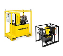
Reservoir 40 – 150 litres
Split Flow Outlets 2,4, 6 and 8
Flow 0,45 – 4,20 l/min
Max. Pressure 700 bar
The electric driven split flow pump is an economical solution for multi-point controlled lifting and lowering applications
- Multiple Outlets with Equal Oil Flow
- 2, 4, 6 or 8 split-flow outlets
- Individual or simultaneous operation of valves, with advance/hold/retract function
- Joystick (manual) controlled or pendant (solenoid) controlled valves
- Flow per outlet ranging from 0,45 to 4,20 l/min at 700 bar
- For double- and single-acting cylinders
- Adjustable pressure relief valve per circuit
- Reservoir: 40 or 150 litres
- All models include pressure gauges
| Number of Split Flow Outlets |
Reservoir Size |
Oil Flow per Outlet @ 10,000 psi |
Pump Model Number 4/3 Valve Operation Advance/Hold/Retract |
Motor Size 460V-3ph 60Hz |
Weight | |
|---|---|---|---|---|---|---|
| (gal) | (in3/min) | Manual (Joystick) | 24 V Solenoid (Pendant) | (hp) | (lbs) | |
| 2 | 5 | 20 | SFP 202MB | – | 1.0* | 190 |
| 10 | 94 | SFP 213MJ | SFP 213SJ | 7.5 | 529 | |
| 40 | 203 | SFP 228MJ | SFP 228SJ | 10 | 1076 | |
| 40 | 305 | SFP 242MJ | SFP 242SJ | 15 | 1160 | |
| 4 | 10 | 33 | SFP 404MJ | SFP 404SJ | 7.5 | 529 |
| 40 | 65 | SFP 409MJ | SFP 409SJ | 7.5 | 1047 | |
| 40 | 101 | SFP 414MJ | SFP 414SJ | 10 | 1076 | |
| 40 | 153 | SFP 421MJ | SFP 421SJ | 15 | 1160 | |
| 6 | 10 | 33 | SFP 604MJ | SFP 604SJ | 7.5 | 529 |
| 40 | 94 | – | SFP 613SJ | 15 | 1213 | |
| 8 | 40 | 94 | – | SFP 813SJ | 20 | 1300 |

Skidding techniques have been used for centuries. Enerpac has applied high-pressure hydraulics to create the Enerpac HSK Skidding Systems. The HSK skidding system is comprised of a series of skid-shoes powered by hydraulic push-pull cylinders, travelling over a pre-constructed track. A series of special PTFE coated blocks are placed on the skid-tracks to reduce friction. The skid shoes are connected by hoses to a hydraulic diesel driven power pack.
Enerpac Skidding Systems are available in several versions:
- HSKB-Series (Skid Shoe Beam) utilizes a tall skid shoe with built-in push/pull cylinders. Skidding direction can be easily switched by flipping a lever on the attached gripper box.
- HSKJ-Series (Skid Shoe Jack) provide the same functionality as the HSKB with the added benefit of having a built-in cylinder for lifting or leveling the load.
- HSKLH-Series (Low Height Skid Shoe) designed with low height skid shoes that can be linked together. The push/pull cylinder (sold separately) is connected to the first shoe. We also offer a support beam for using the thin track that is not fully supported.
To calculate the minimum required capacity per shoe, the entire load has to be able to rest safely on 2 of the 4 shoes. To skid a load of 500 tons, the required skidding system is HSK2500.
| Maximum Lifting Capacity (per shoe) | Maximum Skidding Capacity (ton) |
Model Number | Skid Shoe Height (with track) |
Lifting Stroke | Push/Pull Stroke | Skid Shoe Length | Skid Shoe Weight | Skid Track Width | Skid Track Length | Skid Track Weight | |
|---|---|---|---|---|---|---|---|---|---|---|---|
| ton | Push | Pull | (in) | (in) | (in) | (in) | (lbs) | (in) | (in) | (lbs) | |
| 100 | 25 | 11 | HSKLH900 | 2.44 | – | 23.62 | 59.06 | 135 | 16.37 | 59.06 | 119 |
| 125 | 33 | 17 | HSKLH1150 | 2.44 | – | 23.62 | 59.06 | 135 | 16.37 | 59.06 | 119 |
| 140 | 25 | 18 | HSKB1250 | 12.17 | – | 23.62 | 98.43 | 1,631 | 15.75 | 78.07 | 265 |
| 140 | 25 | 18 | HSKJ1250 | 19.76 | 6.89 | 23.62 | 66.54 | 1,742 | 15.75 | 78.07 | 265 |
| 225 | 29 | 16 | HSKLH2000 | 8.03 | – | 23.62 | 114.25 | 750 | 21.26 | 78.66 | 220 |
| 280 | 45 | 30 | HSKB2500 | 14.72 | – | 23.62 | 118.11 | 2,249 | 23.62 | 76.61 | 640 |
| 280 | 45 | 30 | HSKJ2500 | 23.62 | 6.89 | 23.62 | 70.23 | 3,197 | 23.62 | 76.61 | 640 |

Capacity with 4 towers61 – 1069 ton
Lift Height 3,49 – 14,55 m
Hydraulic gantries are a safe, efficient way to lift and position heavy loads in applications where traditional cranes will not fit and permanent overhead structures for job cranes are not an option. When used with rail systems, hydraulic gantries also provide a means for moving and placing heavy loads. Hydraulic gantries are a cost effective solution for many lifting and rigging applications.
Enerpac offers three series of hydraulic gantry systems:
- Super Lift (SL) series: cost effective models that offers control and stability
- Super Boom Lift (SBL) series: heavy duty hydraulic boom gantry models that go up to 1000 tonne capacity
- Mega Boom Lift (MBL) series: hydraulic boom gantry models which deliver the stability to utilize a 2 leg configuration and can achieve lifting heights over 12000 mm
Enerpac hydraulic gantries have a number of unique features to ensure optimum stability and safety:
- Self-contained hydraulics and electronics
- Intelli-Lift wireless control system
- Self-propelled wheels or tank rollers
- Foldable boom on SBL900, SBL1100, MBL500 and MBL600
- Full range of supplementary equipment: header beams, lifting lugs, side shift, skid tracks
- All gantries are ASME B30.1 compliant
| Maximum Capacity | Model Number |
Retracted Height | Stage 1 | Stage 2 1) | Stage 3 | Transport Height | Base Width | Weight per leg |
|||
|---|---|---|---|---|---|---|---|---|---|---|---|
| (4 legs) |
A |
Max. Height B |
Max. Cap. | Max. Height B |
Max. Cap. | Max. Height B |
Max. Cap. |
C |
E |
(with oil) | |
| (tons) | (ft) | (ft) | (ton) | (ft) | (ton) | (ft) | (ton) | (ft) | (in) | (lbs)2) | |
| 67 | SL60 | 6.58 | 11.17 | 17 | 15.43 | 17 | – | – | – | 31.50 | 2315 |
| 141 | SL125 | 8.66 | 15.01 | 35 | 21.78 | 35 | – | – | – | 36.69 | 4696 |
| 337 | SL300 | 8.87 | 15.11 | 84 | 21.98 | 56 | – | – | – | 34.65 | 7165 |
| 450 | SL400 | 10.39 | 17.14 | 112 | 23.73 | 112 | 29.99 | 52 | – | 49.45 | 10,141 |
| 585 | SBL500 | 9.93 | 16.40 | 146 | 22.66 | 146 | 28.27 | 84 | – | 50.43 | 13,889 |
| 1009 | SBL900 | 16.40 | 27.24 | 252 | 37.09 | 166 | – | – | 7.36 | 55.43 | 29,432 |
| 1178 | SBL1100 | 14.34 | 22.98 | 295 | 31.72 | 190 | 39.38 | 106 | 7.36 | 55.43 | 26,345 |
| 562 | MBL500 | 20.01 | – | – | 42.21 | 141 | – | – | 7.36 | 83.90 | 43,541 |
| 674 | MBL600 | 21.50 | – | – | 47.74 | 169 | – | – | 8.28 | 95.71 | 46,187 |
1) MBL500 and MBL600 are two stage gantries; stages 1 and 2 extend simultaneously and provide full capacity at any height.
2) Weight per tower

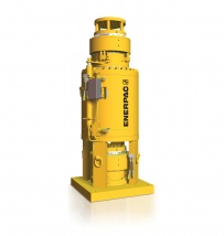
Capacity 15 – 1250 ton
Stroke 250 – 600 mm
Maximum Operating Pressure 350 bar
The strand jack lifting technique originates from the concrete post tensioning principle. A strand jack can be considered a linear winch. In a strand jack, a bundle of steel cables or strands are guided through a hydraulic cylinder; above and below the cylinder are anchor systems with wedges that grip the strand bundle. By stroking the cylinder in and out while the grips are engaged in the anchors, a lifting or lowering movement is achieved.
The motion of the cylinders is driven by hydraulic power packs. They can be electric or diesel powered. Our sophisticated SCC software program synchronizes the motion of the strand jacks and adjusts the motion to the loads per lifting point.
- Full control of lifting and lowering through SCC control
- Two sizes strand diameter: 15,7 and 18 mm
- Complete line of electric and diesel power packs
- Nickel plated telescopic pipes preventing bird caging
- Standard supplied with lifting anchor
- Automated locking – unlocking operation
- Special corrosion treated high endurance multi-use wedges
- Full range of accessories: strand dispenser, strand guide, re-coiler and strand tensioner
| Strand Diameter | Capacity* | Model Number |
No. of Strands |
Stroke | Weight |
|---|---|---|---|---|---|
| in (mm) | (ton) | (in) | (lbs) | ||
| 0.62 (15.7) | 34 | HSL3006 | 3 | 18.9 | 1,102 |
| 79 | HSL7006 | 7 | 18.9 | 1,411 | |
| 225 | HSL20006 | 19 | 18.9 | 2,860 | |
| 337 | HSL30006 | 31 | 18.9 | 4,820 | |
| 562 | HSL50006 | 48 | 18.9 | 6,930 | |
| 0.71 (18) | 17 | HSL1507 | 1 | 9.8 | 220 |
| 51 | HSL4507 | 3 | 18.9 | 1,102 | |
| 67 | HSL6007 | 4 | 18.9 | 1,433 | |
| 112 | HSL10007 | 7 | 18.9 | 1,874 | |
| 225 | HSL20007 | 12 | 18.9 | 3,086 | |
| 337 | HSL30007 | 19 | 18.9 | 4,290 | |
| 506 | HSL45007 | 31 | 18.9 | 6,724 | |
| 731 | HSL65007 | 43 | 18.9 | 8,690 | |
| 955 | HSL85007 | 55 | 18.9 | 11,023 | |
| 1124 | HSL100007 | 66 | 18.9 | 16,865 | |
| 1405 | HSL125007 | 84 | 23.6 | 18,298 |
* Capacity is based on 2.5 minimum safety factor over strand breaking load. Download brochure for details.
| Theoretical Lifting Speed (ft/hr)* | ||||||||
| Strand Jack Capacity (ton) |
Motor Size(hp) | |||||||
| 3.0 | 7.5 | 10 | 20 | 25 | 40 | 50 | 74 | |
|---|---|---|---|---|---|---|---|---|
| 17 | 52 | — | — | — | — | — | — | — |
| 34 | 39 | 43 | 52 | — | — | — | — | — |
| 51 | 39 | 43 | 52 | — | — | — | — | — |
| 67 | 30 | 33 | 43 | — | — | — | — | — |
| 79 | 30 | 33 | 43 | — | — | — | — | — |
| 112 | 26 | 30 | 36 | 52 | — | — | — | — |
| 225 | — | — | 20 | 33 | 39 | 49 | 49 | — |
| 337 | — | — | — | 23 | 26 | 36 | 36 | — |
| 506 | — | — | — | 20 | 23 | 33 | 33 | — |
| 562 | — | — | — | 20 | 23 | 33 | 33 | — |
| 731 | — | — | — | — | — | 26 | 26 | 49 |
* Theoretical lifting speeds. Each application should be evaluated to determine the optimum lifting speed for maximum safety and control. Contact Enerpac for more information.
Typical Configuration
- Set of 4 strand jacks
- 4 Power Packs
- 4 fixed anchors
- 1 SCC Control System
- 4 data cables 50 meters
- 4 Hose sets, standard length 5 meters each
Accessories
- Power Packs
- Strand Guide
- Strand Recoiler
- Strand Dispenser
- Strand Wedges
- Heavy-Lifting Strand
CUSTOM PRODUCTS
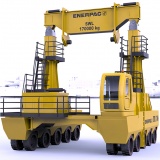
Vertical Cask Transporter
Safely handle and transport casks for dry storage of used nuclear fuel
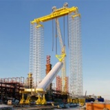
Self-Erecting Tower (ESET)Pumps
A free standing gantry system that enables you to build a tower with standard modular components from the ground level.
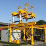
Strand Jack Gantries
A steel structure to facilitate erection, skidding back and forth and sideways of heavy loads up to 1100 tons.

Rotor Removal and Installation Systems
Hydraulic system for pushing, pulling and positioning a generator's rotor (field) at multiple heights.
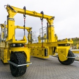
Travel Gantry
A self-collapsing rubber tyre gantry with a 60 ton lifting capacity
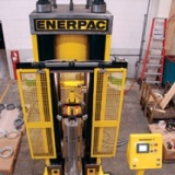
Custom Hydraulic Presses
Manufactured with a diverse range of configurations to fulfill a broad range of applications.
REACH US THROUGH OUR
ADDRESS
4659 & 4661 Kathrina Building Arellano Street, Palanan, Makati City Philippines 1235
TELEPHONE
(02) 832-0560 / 832-0586 / 832-0602
Mobile
0927-243-6655 / 0918-903-6020
info@hydrauking.com
FAX
(02) 8334975